Archive for March 2012
 Weekend “project”
I hoped to catch up with some of my backlog this weekend but it is unlikely to happen. I am a member of our Student Government Association (SGA) and I will be attending a state-wide conference with them until Sunday.
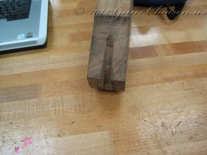
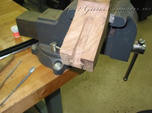
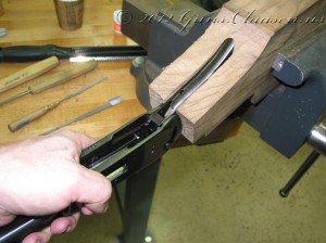
 Winchester 94: Inletting the bottom of the stock, starting to remove wood from the blank
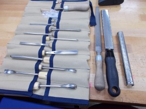
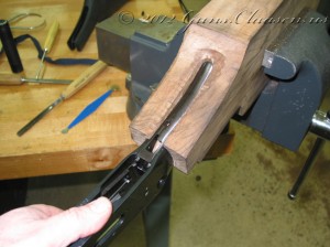
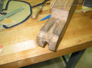
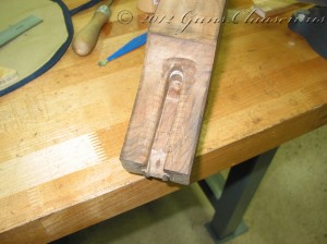
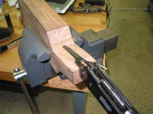
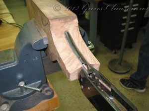
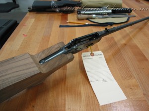
After I completed the inletting on the top tang, I started with the lower tang. The lower tang is not fixed and that makes life a little more difficult. Furthermore, the screw that holds the receiver in the stock passes through the top tang and secures in the bottom tang in a blind hole on this model. So, not only did I have to work this down to the correct depth, I had to be really careful about how the hole will be drilled for the screw. I am showing a select few pictures of this process but it did take some time! First though, a picture of some of the tools I use. This shows the chisels, a #49 cabinet rasp and a micro plane. I some of the top bags of the tool roll is some scrapers and some needle file rasps.
On to the stock work:
And finally, after many hours of work I am done.
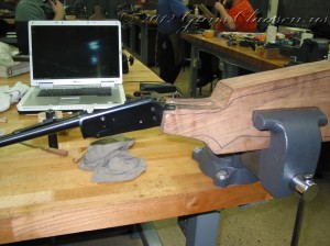
Next, I drilled the hole for the tang screw. No pictures of this, but I must admit that my first pilot hole was incorrect. Luckily, it was a minor mistake. Then the rifle is mounted back in the stock blank. This is the point where I start removing all the bits that do not look like a stock!
I started by removing material from the top of the tang area:
Then from the bottom tang area:
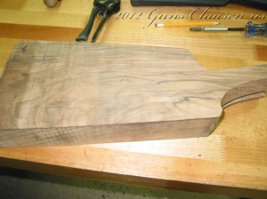
After I completed this, I removed the rifle from the stock blank again and used the original stock as a rough template. If you look carefully you can see that outline on the wood.
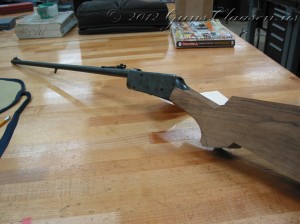
After I created the rough outline, I used an electric bandsaw to remove the excess wood and mounted the rifle back into the stock.
This is a good place to wrap up this post. In the next post of the series, I will do some layout work and start forming the stock.
 Mauser project: The beginning
Even though the course require that I build a minimum of three rifles, an additional requirement is that one of these must use a military surplus Mauser action. There is many options available that can be used and the one I chose was M48A Mauser. These were built in Yugoslavia by Zastava and is a version of the FN designed Mauser Model 1924. Thank you to Matt for selling me the rifle for this project. I hope you like what I am doing with it. The rifle was in good condition and as I started working on it, realized that it had been refinished by an arsenal and had not seen much use since then. The only part of the old rifle that I need is the action and the bolt. I am building this rifle as a hunting rifle and when finished, will be chambered in .257 Roberts and have a one-piece wood stock made by me.
Please note that this work took place earlier this semester.
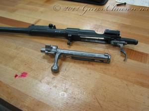
I started by disassembling the old rifle.
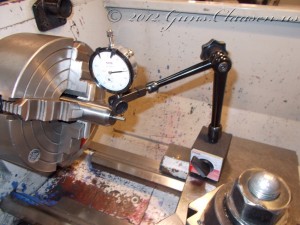
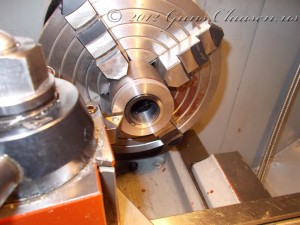
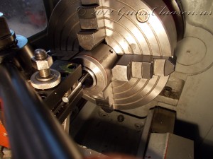
Then the action was mounted in a lathe and trued.
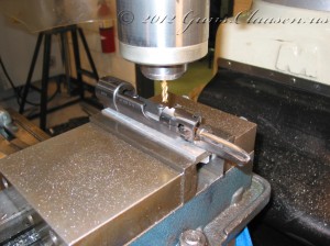
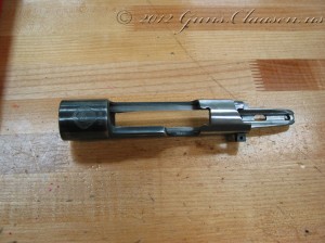
On the M48A action there is a bump on the rear of the receiver. It has a slot where cartridges on stripper clips can be inserted. However, this just does not look good. I removed the hump and smoothed the metal work.
Although the stripper clip slot can still be seen, I am leaving it as such for the time being.
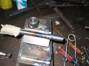
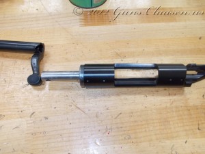
My attention then turned to the bolt. I started by heating the bolt handle and forging it into a new, more graceful shape. The picture also shows two tools I made in the first semester. Screwed in the back of the bolt is a bolt mandrel which (in this case) helps to draw heat away from the bolt body. The bolt sits inside a bolt bending block.
The next picture was taken during the process. I still needed to sweep the handle backwards a little.
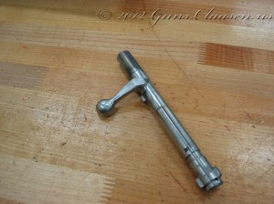
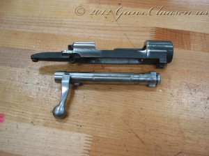
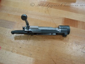
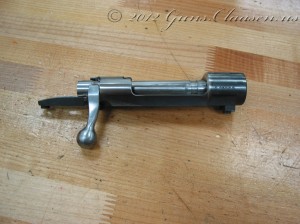
The next three pictures show the bolt handle after I swept the handle back, the receiver and how they fit together. I had to cut a small notch in the receiver body to allow the bolt to fully close.
So far, so good!
 Remington 700 project: Action blueprinting
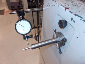
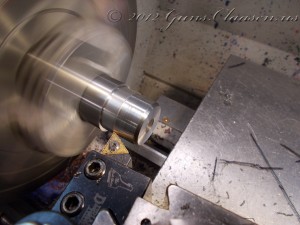
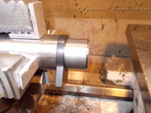
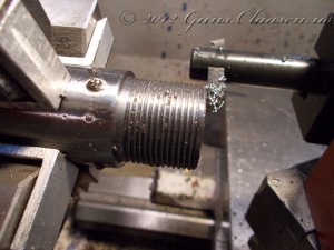
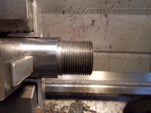
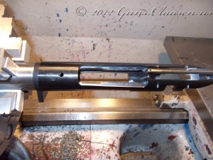
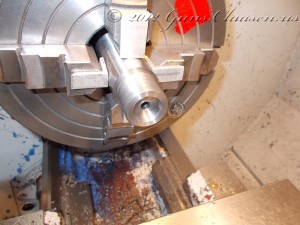
With the blueprinting work on the bolt finished, it is now time for the receiver. As with the bolt, I use a fixture to clamp the receiver in the lathe and center the work. Run-out on this setup was slightly better than the bolt fixture. The rod sticking through the receiver is only used to measure run-out. It is removed (actually pushed back as it fits really tight) when the work starts.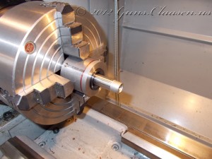
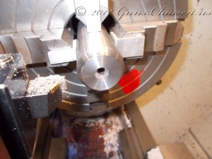
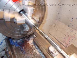
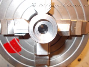
Here is the work halfway done. This photo was taken after the first cut and you can see that the face of the receiver is not quite square. Even though the factory has good tolerances in their manufacturing process, you can get better results with a little extra work.
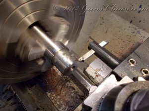
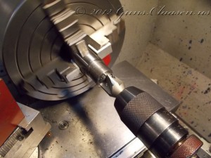
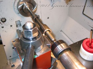
The next step is to square and true the inside of the receiver. I use a small boring bar to get inside the receiver. It is difficult to see in the first picture what I am cutting, but this is done to square up the recoil lugs inside the receiver.
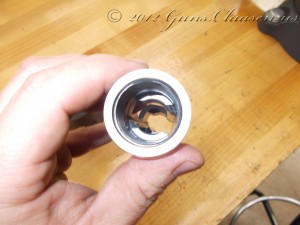
The next step is to use a tool to lap the bolt lugs onto the recoil lugs. The lapping tool is screwed into the receiver where the barrel would normally go. It has a spring-loaded center part and when the bolt is inserted into the receiver and locked into the closed position it will push the bolt lugs against the recoil lugs in the receiver. Lapping compound is a fine grinding paste and by applying some on the back of the bolt lugs, inserting it into the action and opening and closing the action, the lapping compound will slowly grind these surfaces to make perfect contact with each other. The pictures show the receiver with the lapping tool inserted, the bolt after lapping (you will note wear on the dark part of the bolt due to the grinding action of the lapping compound) and the inside of the receiver showing the recoil lugs.
Next up is the barrel and I will show the work on that in a new post.
